 Power Circuit |
 Regulating Circuit |
Proposal of a cooling circuit for 1 ECAL Super Module
17/01/2002
Arnaud Hormière ST-CV
=> Introduction
=> Former Work
=> New parameters
=> Philosophy
=> Hydraulic Plans
=> Temperature Measurement
=> Process Regulation and Control
=> Installation in zone H4
=> Budget
=> Industrial Contacts
Several steps of the development of the ECAL subdetector have been delayed, essentially due to the difficulties encountered in manufacturing the final electronic cards (VFE). The design of this card has evolved, with consequences on the power dissipation per channel of the detector. This has major consequences on the dimensions of the cooling circuit dedicated to this detector. It implies changes in the cooling station (pumps, heat exchangers...) and all along the routing for the pipes, also in the detector. The "power to cool" by the cooling circuit has to be reviewed, as changes in the electronic card may change the dissipation in the Low Voltage cables, supposed to be cooled by the Power cooling circuit of ECAL (some information on the former values can be found in "Power to cool" review).
Some work has been done concerning a cooling circuit for a Super Module, including a partial Cost Estimate. This work is considered as a base for the current proposal.
Formerly, the heat dissipation per channel for the electronic card was set to 1.7. It
is now supposed to be 2.5 W/ch, but the design value will be 3 W/ch. These values
were given during the 21st SPES meeting, 14 November 2001.
We will calculate the new heat dissipation in a Super Module (1700 channels) and the
consequences on the flow rate.
Total heat to remove: 5.1 kW. (90% Power circuit and 10% Regulating circuit).
Flow rate:
Once we have the heat to remove by each circuit, we compute the flow rate with the
temperature difference allowed between the inlet and the outlet of the detector for each
circuit. However, some parts of the circuit inside CMS have already been designed and the
diameter of some pipes has been fixed (Crack 53°). As we don't want velocities bigger
than 2 m/s, it gives a limit value for the flow rate.
Values to be used for all EB, 36 Super Modules(O.Teller EP/CMA): Power: 10 l/s and
Regulation: 50 l/s.
Pumps:
The pumps will be equipped with variable speed drive (see below). To design these pumps,
we have to give a range of flow rate and head. We design them such as the can provide
twice the nominal flow rate given above. For the head loss, it is computed from the
circuit path.
Pipes diameters
Calculated to have a maximum speed of 2 m/s with the maximum flow rate.
Pumps power:
The maximum pump power is calculated as follow: Efficiency*Hydraulic power delivered.
Efficiency=1/0.7 and Hydraulic power=Maximum Flow rate * Maximum head.
Heater:
Designed to increase the temperature with 0.2K for nominal load, witha maximum of 0.3K.
Heat to remove:
The heat to remove comes from the detector and the pump (and also the heater for the
regulating circuit). We use the maximum pump power and the add a margin that correspond to
a change in temperature of 1K for the power and 0.1K for the regulating (equivalent to 20%
margin).
As there is two heat exchangers and two loops in the regulating, we have to increase the
heat to remove for the heat exchanger to the primary. This can be estimated to a 10% duty
margin on the heat exchanger.
Flow in the primary:
It is possible to estimate the flow rate in the primary for both circuits, assuming a
temperature difference of 6°C. It will give the minimum
flow rate. The maximum can be estimated to be twice this minimum flow rate, it
is mainly for pipe dimension's safety margin.
The pressure
drop between inlet and outlet line is estimated to 3 bars in the caverns. The value
of this pressure drop for
the prototype will depends on the location of the cooling station itself.
| Power circuit | Regulating circuit | |
| Heat dissipation in ECAL | 4.59 kW | 0.51 kW |
| Flow | 0.28 l/s | 1.39 l/s |
| DT | 3.95 K |
0.09 K |
| Pump Flow rates | 0,2...0,6 l/s | 1,2...2,8 l/s |
| Pump Pressure Drops | 5...10 bars | 1,5...4 bars |
| Pipe diameter | DN20 | DN40 |
| Pump power | 0.8 kW | 1.6 kW |
| Resistance | 1.8 kW | |
Heat to remove (no margin) |
5.4 kW |
3.3 kW |
| HE used values | 7 kW | 4.5 kW (5 kW) |
| Flow in primary | 0,28...0,56 l/s DN20 |
0,18...0,36 l/s DN15 |
| Temperatures encountered in the circuit for nominal flow and load | ||
Tin |
18.0°C |
18.0°C |
Tout |
22.0°C |
18.1°C |
T after pump |
22.4°C |
18.2°C |
T after HE |
18.0°C |
17.8°C |
Remark:
It is important to notice that some work has to be done concerning the power circuit. It
is presently under development and some constraints may increase the flow rate. The main
reason is to allow a minimum Reynolds number in the cooling tubes for an efficient
heat transfer.
It is difficult to find a level of precision of ± 0.05 K and a good repeatability in the measurement with the classical temperature measurement devices used in industry, i.e. probe and transmitter. Several companies have been consulted, and large ones like ABB Automation and Rosemount, but the solution proposed is not sufficient. The problem doesn't come from the probe itself (even if it must be of good quality and with a low response time) but from the transmitter, that measure the resistance of the Pt100, and convert it to a temperature.
For a Pt100, in a first approximation, we can say that a variation of 0.4 ohms of the resistance is equivalent to a variation of 1K of the temperature. If we want to measure 0.01 K of variation accurately, the transmitter must be able to measure 0.004 ohms, that is, for a measure of ~ 100 ohms, 0.004 % of error on the measurement.
An alternative solution could be to use apparatus used in laboratory, like
the acquisition unit from Agilent Technologies
(34970A). It is a precise multimeter with a multiplexer, that allow several
measurements (Data sheet) .
It gives far better results compared to the transmitters and for a better price.
The problem with this device in our application comes from its communication
with a PLC. It is possible through the RS232 port (in ASCII), but some development has to
be done to ensure the communication.
Process Regulation and Control
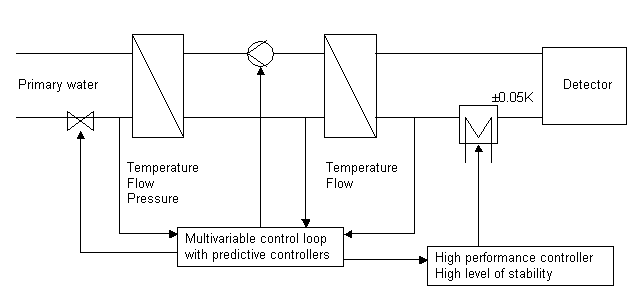
The level of performance required is far above the classical needs. To reach such a level, advanced and high performance control has to be used (multi variable, predictive controller...).

Process control diagram
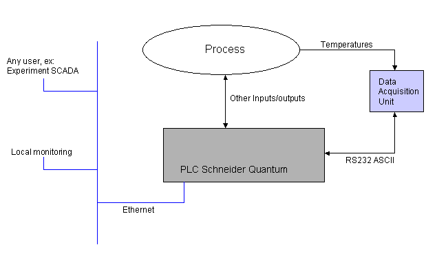
To ensure such regulation, and with the same level of reliability
as normal automated process, the best solution is to use a Quantum PLC from
Schneider. It is already used at CERN for some applications (ST/CV cooling
towers), and is foreseen for the control of LHC cryogenic supply. It is a very
powerful automaton for calculation, and it is design for advanced control (with
build in predictive loops and libraries).
The following diagram shows the control architecture, including the data
acquisition unit for temperatures.

Control architecture
Remark: For this topic, a non negligible help was provided by D.Blanc and M.C. Morodo Testa from ST/CV.
Installation in zone H4 of B.887
Cold source
The activity of calibration in the H4 zone will request some cooling power apart
from the cooling of ECAL Electronic cards, for ventilation in the area and for
other electronic devices.
Nowadays, this cooling power comes from the chilled water circuit of the CERN
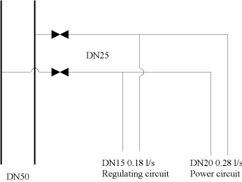
facilities. The installations are connected to this circuit through DN50 pipes (Situation
map at 10 December 2001). The cooling station can be installed either inside
the barrack or outside, depending on the surface needed and available.
A connection to this actual DN50 pipes has to be foreseen for the heat
exchangers primary water.

Demineralised water access
The cooling circuit will be open and reconnected when passing from a super
module to another, and the new super module will have to be filled with water.
This operation will be done at least 36 times, as there is 36 super modules. For
this reason, it must be possible to fill easily the circuit. A connection has to
be done between the demineralised water network in building 887 and the cooling
rack.
Gas for purging and expansion vessel
The installation of an expansion vessel that can be filled directly with
demineralised water and also linked to a gas source is a possible solution. It
is also an indicator of leakage, if some gas is needed to maintain the pressure
in the vessel under operation.
The cooling circuit will also be purged when passing from a super module to
another, to empty the super module that has been tested. This operation can be
done with an injection of nitrogen. In this case, a gas circuit has to be
installed in the H4 area.
Purging scenarios for SM
Not yet determined
This budget is for a solution using a Quantum for regulation and control. It includes manpower and material, also some piping in the H4 zone.
The price of the Power circuit is smaller than the price of the regulating circuit. It has less material, so less handwork on it and is not insulated.
The Control and regulation is a major part of the cost. In this case, it is not linked with the size of the process, but with its complexity.
| Object | Price in KCHF |
| Power circuit Material | 20 |
| Power circuit assembly | 10 |
| Regulating circuit Material | 35 |
| Regulating circuit assembly | 30 |
| Electrical material + assembly | 15 |
| Installation in H4 | 10 |
| Control (PLC Quantum, PC, Software) | 15+5+0=20 |
| Development and programming (PC, PLC) | ??50?? |
TOTAL: ~200 KCHF
Details: (without control and regulation costs) PDF File