Ecal regulating circuit: Principle review
21/06/2001
=> Requirements
=> Key Ideas
1 Pump position
2 Flow splitting
3 Immersion heater
4 Mixing, buffer tank
=> Heat to remove
=> Temperature differences in the circuit
=> Different chillers
=> Proposal
=> Discussion
=> Contacts
The sub-detectors components require a good temperature stability to give precise
results. This stability has been set to ± 0.05 °C.
The detectors cooling systems usually use deionized water because of the
magnetic field. It is the coolant that we will use.
The precision stability required in the sub-detector implies that such a precision can be
achieved in a cooling station. Furthermore, the flow rate is very important, due to the
temperature difference allowed between the entrance and the exit of the sub-detector
(equal to the precision, 0.05°C). This high flow rate makes the precision more difficult
to achieve.
The cooling system is supposed to work with a constant load due to the dissipation in the
sub-detector and to the pump. The perturbations from the ambient should be reduced by the
use of a very thick insulation (link).
Some other perturbations can come from the heat exchange between pipes and cable, mainly
with low voltage cables, along the path of the tubes inside CMS. These perturbations are
difficult to predict, because the path is not well known (at the moment), and also because
there are several parameters to take into account.
During operation, there is a modification of the load that is predictable, it is the one
that will occur in case of partial shutdown of the electronics. It means that the maximum
return temperature is obtained when the electronics run normally.
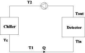
1 - The pump produce some heat that can disturb the temperature stability of the fluid. For this reason, it has to be placed after the detector and before the cooling if we follow the fluid circulation.

In this condition, if we consider that no perturbation comes from the ambient, Tin=T1=Tc and T2=Tout+DT, with DT the temperature variation due to the pump. The temperature variation that can be due to the chiller, around Tc is transmitted to the detector:
![]()
2 - The return flow from the detector will be split in two parts. One part will be cooled down and then mix again with the other part, like in the schema below. The flow separation will be ensured with a regulating valve. The flow going to the chiller is reduced and the temperature difference between the inlet and the outlet of the chiller is increased.
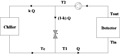
Once the coefficient k (between 0 and 1, typically 0.25) is defined, the regulating
valve ensure the splitting and no further operation on the valve is needed.
The former relations between T1, Tin, Tout and T2 are still true. Now Tc is different from
T1. We have the relations:
![]()
![]()
With a value k of 0.25, we reduce by 4 the influence of the variations at the outlet of the chiller (due to the regulation process) to the temperature Tin at the entrance of the detector.
Remark: With this configuration, the regulation of the chiller will be made with Tc as a reference. But Tc depends on T1 (set point) and T2, if we want T1 to stay constant with T2 variations. We will see later if Tc has to be parameterized or if a constant value can be acceptable. The disadvantage of this solution is that the chiller regulates Tc and not T1. The mixing of the two flows has to be optimized.
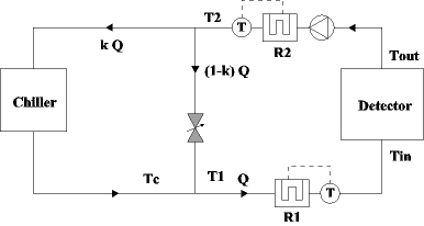
3 - The best way to control the temperature of a flow is to use an immersion heater. This power dissipated in this resistance and given to the fluid is regulated via the temperature after this heater, like in the following drawing.
![]()
The problem is that the regulation cannot anticipate an incoming
variation. However, the time response of this system is faster than the usual thermal
variations, that allow in many case a good regulation. According to Eurotherm automation (Info), a company specialized in thermal control, the precision of ± 0.05 °C can be achieved
under some conditions (they have experience in such level of precision). In any case, the
regulation has to be parameterized on the model itself to adjust all the parameters.
This allow us to have a chiller with a precision less important, ±0.1°C should be
a sufficient precision.
The good position for the heater (R1) would be after the mixing, to reduce variations
temperature at Tin.
We can put another heater (R2) after the pump, to limit the variation on T2, and then ease
the regulation of the chiller on Tc=constant. This is optional if we can achieve a
sufficient precision at Tin with the first heater while variations at T2 are not reduced.
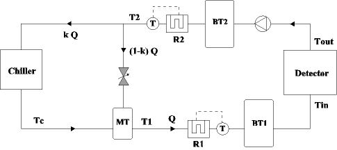
4 - A Buffer tank can be placed on the circuit. Its goal is to reduce the amplitude and the rapidity of temperature variation that will arrive to him. It has also good properties for the mixing. The main problem is that the tank cannot be placed between the active and the measuring component of a regulating loop (ex: not between a resistance and the thermal sensor associate). The reason is that the tank introduce a dead time that destabilize the regulating loop.
Placing tanks seems not necessary, but it can increase the general efficiency of the system in front of perturbation. A mixing tank (MT) can only be used if the chiller is working with Tc as a temperature to regulate and not T1. Two buffer tanks can be considered, one (BT2) in front of R2 to reduce variations coming from the load or the pump, another (BT1) after R1 to reduce variations incoming to the detector.
| Flow | Heat produced | |
| EB | 50 l/s | 10 kW |
| EE | 10 l/s | 4 kW |
| Pump | 30 kW | |
| Total: | 60 l/s | 44 kW |
The heat produced in the Ecal endcaps is twice smaller than in the barrel but the flow is 4 times smaller. It is a result of different requirements, 0.05 °C for the barrel and 0.1°C for the endcaps.
For the pump, the calculation is made for an air cooled pump. The heat produced
correspond to the energy given to the flow by the pump, that is gmH, with g the gravity, m
the mass flow rate and H the pressure head given by the pump. The pressure head is
evaluated to 50m.
In the following, we will consider that all the power given by the pump is transformed in
heat between Tout and T2, which is not true. Due to the head loss, there is a constant
temperature rising. However, it is easier to make the calculation and not forget this heat
source.
Temperature differences in the circuit
We take the following figure for an example of temperature calculation, k=1/4.

We set the value of Tin to 18°C. An acceptable precision for T1 would be
±0.1°C (maximum deviation). So we set the value of T1 to 17.8°C. The difference between
T1 and Tin will be given by the resistance R1.
Tc will change depending on the value of T2. The maximum value of T2 correspond to
"normal" working conditions for the detector, and the minimum value to a
shutdown of the electronic inside Ecal. It is Tc that is regulated by the chiller, but
with a variation in the set point. So variations due to the regulation should be reduced
by the mixing, possible in a tank, as T1 is not the regulated value.
The temperature difference between Tin and Tout is due to heat removal, and head loss. The
latter is not included in the calculations. The pressure drop inside the sub-detector
should be reduced to limit this temperature rising (2 bars will rise the temperature by
0.05°C).
| Tin | 18°C | |
| Power dissipated in the detector |
14 kW | 0 |
| Tout | 18.06°C | 18°C |
| T2 | 18.18°C | 18.12°C |
| Tc | 16.67°C | 16.84°C |
| T1 | 17.8°C | |
| Power of R1 | 76 kW | |
In a second time, we consider that Tc is set constant, and that T1 will change with the variations of T2. This will help the regulation of the chiller, because it only has to stay at a constant value. The disadvantage is that the difference on T1 will have to be removed by the resistance. It may reduce variations during transitory on T1, because variations on Tc should be less important. It also allows a mixing tank.
| Tin | 18°C | |
| Power dissipated in the detector |
14 kW | 0 |
| Tout | 18.06°C | 18°C |
| T2 | 18.18°C | 18.12°C |
| Tc | 16.75°C | |
| T1 | 17.82°C | 17.78°C |
| Power of R1 | 71 kW | 81 kW |
MS-Excel File (used for these calculations)
The first solution demands a very good regulation loop on the chiller and allows a
mixing tank, because the set point is Tc. The problem comes from reading the value of T2
precisely.
If a chiller can be found that works without the splitting with a good accuracy, it
must be the solution taken.
The second solution, Tc fixed, seems better in terms of stability of the process. It is
however "blind" to temperature variation. The regulation of the resistance has
to be high performance.
- On the cooling circuit prototype, for the Module0 of Ecal (link) the chiller is a Lauda. This is a precise
chiller cooled by air. It is efficient for the module0, we can reach the precision
required. However this device doesn't exist for power encountered in the final version (
>40kW).
After some research, we have been able to find a company, Eurodifroid (info)
that can provide a chiller for the required power and a precision of ±0.1°C, which
should be enough if an immersion heater adjust the precision to ±0.05°C. It consist of a
cooling circuit with a compressor and an evaporator, that exchange heat with a tank. The
tank can also be heated by a thermal immersion heater.
This solution present the advantage of being ready to use as we buy it. On the other hand,
the price is high, the reliability reduced due to the complexity. We also have less
information on the process as it is managed by this apparatus.
- At CERN, there is a production of chilled water. The chiller can consist of a heat
exchanger and a regulating valve. After some discussion with the society Samson (info), the best system to reach a good temperature stability (as
0.1°C) is a double heat exchange circuit.
Primary can be either chilled (6°C) or mixed water (13°C).
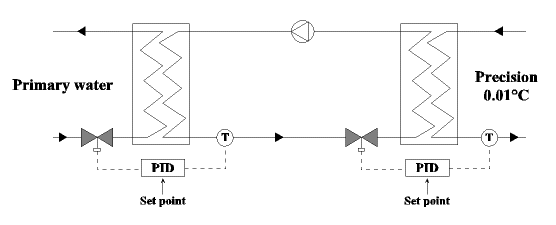
It costs twice the normal price of a heat exchanger system, but it gives good results
in terms of stability, according to Samson people.
Such solution is reliable, as the only critical part is the pump. It gives us a total
access to the heat exchange process. Furthermore, the high flow should not be a
restriction for this chiller. The temperature difference between the inlet and the outlet
of the heat exchanger will be small (around 0.3°C).
The second solution present the advantage of reliability and simplicity. The precision
are the same in both case. A chiller composed of two heat exchanger seems to be the best
solution.
After this review, the proposal is as simple as possible. We assume that the heat exchanger regulation will be good enough, and that the resistance will obtain the desired precision.

Temperatures:
We set Tin to be 18, with a supposed precision of 0.05°C. Tc is set to 17.8, with a
precision of 0.1°C.
| Tin | 18°C | |
| Power dissipated in the detector |
14 kW | 0 |
| Tout | 18.06°C | 18°C |
| T2 | 18.18°C | 18.12°C |
| Tc | 17.8°C | |
| Power of R1 | 76 kW | |
If the efficiency of the heat exchanger regulation is not good enough, we can try the
solution of flow splitting.
If there are some temperature variation that are too fast to be corrected by the
regulation, we can add some buffer tank.
This model has to be tested to be sure of its efficiency. A reduced scale model can be considered, for example at the size of a super module. Rough estimation of costs for a reduced model: 20 000 CHF.
- Noise measuring temperature
- What type of regulation
- Efficiency of splitting and mixing (needed for the chiller?)
- Resistance efficiency (angle phase control with 80 kW, High frequencies?)
- HE regulating loop
- Eurotherm Automation SA, 6, chemin des joncs, BP55, 69572 Dardilly CEDEX
Carlos Sousa
Specialized in thermal control and regulation
http://www.eurotherm.tm.fr/
- Eurodifroid, 49190 Seiches sur le Loir
Mr Chabassol
Specialized in Industrial process cooling
http://www.eurodifroid.fr
- Samson Regulation SA
Jean Claude Marchetto
Specialized in valve regulation
http://www.samson.de/esamson.htm