Study of SE and EE thermal shields efficiency towards beam area temperature
01/02/2001
=> Position of the problem
=> Modelisation
=> Hypotheses and characteristics
=> Calculation page (in french) Internet Explorer required.
=> Conclusions
=> Remark (15/08/2001)
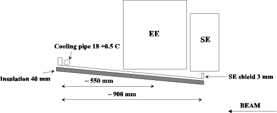
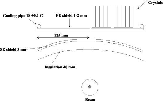
The aim of this study is to know the effect of a difference of temperature between the EE environment (18°C) and the beam environment (21°C) on the temperature stability of the EE crystals. There are two thermal shields between the beam environment and the EE, the SE shield cooled with 18 ± 0.5 °C and the EE shield cooled with 18 ± 0.1 °C

Cut view of the Endcap in the direction of the beam

Cut view of the Endcap in the direction perpendicular to the beam
We choose to make a first order approach considering only a one dimensional fin. It allow us to calculate easily the temperature distribution.
We first consider a fin that is supposed to be representative of the SE shield temperature distribution. T0 and Text is known as well as h, L and the properties of the materials.

Then we consider a second fin that will represent the EE shield, without insulation.
Hypotheses and characteristics
For the first fin:
T0=18.5°C and Text=21°C
h=10 SI. Values are usually between 5 and 10 so we take a value that ease the heat transfer (which is unfavorable).
L=900mm.
Material 1 is aluminium thickness of 3mm and conductivity 300 SI.
Material 2 is normal inulation (not determined) of 40mm and conductivity is set to 0.06 SI. Usual insulation can be found with (0.05).
The temperature is supposed to be constant through the thickness of material 1, convection only between air and material 2, material 1 upper part adiabatic (that increase mat1 temperature), perfect contact between mat1 and mat2.
Hypotheses are made to have an unfavorable case.
For the second fin:
T0=18°C
Aluminium, Thickness=2 mm, length=125 mm
We consider convection in the space between the SE and the EE even if it seems that the Rayleigh number is too small to allow the creation of convective movements.
We consider that the air below the second thin is at the maximum temperature encountered in the Se shield.
Calculation page (in french) Internet explorer required.
Mathcad File (used for the calculations).
The temperature in the EE shield is not increasing more than 0.1°C with a +3°C difference between EE and beam environment. The thickness of the aluminium shields is important. If the EE shield thickness is 1 mm, the increase in temperature 0.17°C.
The model is not a complete model but we have taken every time the unfavorable case and it can give a good idea of the real situation.
The aluminium conductivity used above (300 SI) was too optimistic,
in fact it is closer to 200 SI.
With this new value, the temperature in the EE shield increase of 0.11°C.
This is almost the same result as before, but I preferred to mention it
in case of further remarks.
Calculation page (in french) Internet explorer required.
top