| ECAL Overview |
 |
15/06/01
=> Presentation
=> Cooling system principle inside ECAL
=> The cooling station
=> Pressure drop
=> Cooling principle
The module is a prototype facility made to study the behaviour of the cooling of ECAL, one sub-detector of CMS. More precisely, it consist of one module of the Ecal Barrel.
| ECAL Overview |
 |
Every super module consist of 4 modules (as we can see in yellow in the above figure). In the module 0 facility, only one module has been installed inside a super module structure. It is cooled by a station dimentionned specifiquely for it.
Hydraulics parameters and temperature in several points are monitored and recorded via an acquisition facility.
The module

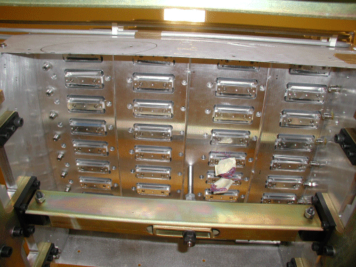
From below:

We can see on the left and on the right the holes for the regulating cooling circuit.
The long and narrow holes are made for the connection between the front electronic (linked with the crystals) and the readout boxes.

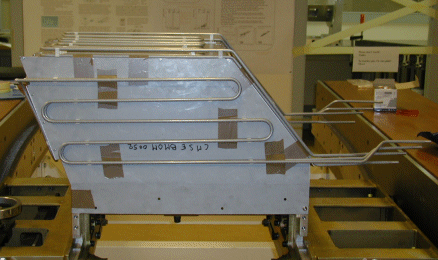
Same image as before but with the return of the regulating circuit, with the thermal shields in copper. See the cooling system principle for more details.
Inside the Super module structure
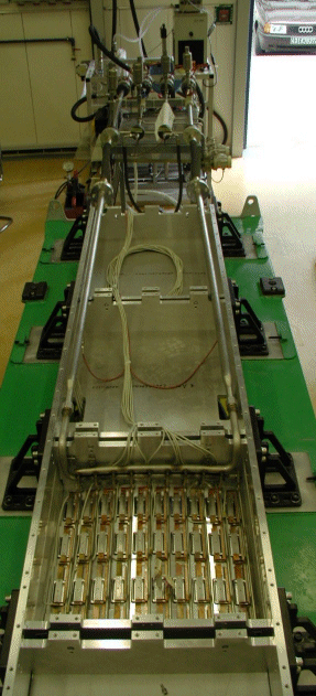
We can see below a super module structure (in aluminium) on its support (green and Yellow). On the right the cooling station.

From above, we can see that only one module is installed in the super module.

Cooling system principle inside ECAL
The goal is to achieve a very hight temperature precision (± 0.05 °C) around the crystals and the photodiodes that are stuck at the end of the crystals (not represented here). The heat source is the electronics inside the Read out boxes (RBX). The cooling circuit has to remove this heat before it reaches the crystals.
It has been decided to split in two parts the cooling.
- One circuit, the Power circuit (Precision ± 1°C) has to remove 90% of the heat produced in the RBX. It runs between the boxes and is linked to them with a copper braid (for the moment) that will conduct the heat from the box to the cooling pipes. The circuit is designed for a temperature difference between inlet and outlet of 5°C. Speed in the pipes, 2 m/s.
- The second circuit is called Regulating circuit, because its precisions is very important (± 0.05°C at least) to ensure the precision around the crystals. The flow goes first in the aluminium grid for a "thermalisation" and the return pipes are welded on copper thermal shield that are supposed to collect the residual heat (10%) produced by the electronics. It is designed for a temperature difference between inlet and outlet of 0.05°C. Speed in the pipes, 2 m/s.
ECAL Cooling principle |
|
For the Power circuit, the coooling is provided by the chilled water circuit of the bildimg, linked to a heat exchanger.
For the regulating circuit, it is provided by a Lauda chiller that is cooled with the air.
Hydraulics Schemas of the installation
Picture:

Acquisition system
It consists of an automaton (Leroy) that collect all the data in an
analogical form (4-20 mA), translate them to a numerical form (16 bits) and transfer them
to a PC via an ethernet link.
These datas are then displayed using the software Wizcon. Real time values and plots are
available to follow the evolutions.
This software store the data in a file for every day. The datas are accesible directly on the PC and can be remotely sent via intranet network to another computer.
The pressure drop have been calculated for a Super module, before the
construction of the module0.
To get the value for a module, we keep the head loss, but we reduced the flow by 4, as the
4 modules are in parallel in a Super module.
It gives us the following results, computed by G.Peon (ST-CV).
| Circuit | Flow | Head loss |
| Regulating | 0.347 l/s | 0.14 bars |
| Power | 0.0347 l/s | 0.73 bars |
In fact the circuit in the Module0 are different from the calculation, in terms of
diameter.
The power circuit change from Dinside=4mm to Di=5mm.
The regulating circuit had a change from Di=6mm to Di=7mm for one half of the path.
As we know: ![]() , so we can calculate the new values of computed head loss. It
is not exactly true due to particular head loss (elbows...) but it gives a good
approximation.
, so we can calculate the new values of computed head loss. It
is not exactly true due to particular head loss (elbows...) but it gives a good
approximation.
| Circuit | Flow | Head loss |
| Regulating | 0.347 l/s | 0.1 bars |
| Power | 0.0347 l/s | 0.24 bars |
Values read during Module0 activity (15/06/01). These values were difficult to obtain, because of a calibration of the pressure transmitter badly taken into account (more info).
| Circuit | Flow | Head loss |
| Regulating | 0.36 l/s | 0.13 bars |
| Power | 0.04 l/s | 0.38 bars |
As the head loss depends on the flow rate, ![]() , we can compare these values for the same flow
rate, wich gives us:
, we can compare these values for the same flow
rate, wich gives us:
| Circuit | Flow | Head loss calculated | Head loss observed |
| Regulating | 0.36 l/s | 0.12 bars | 0.13 bars |
| Power | 0.04 l/s | 0.32 bars | 0.38 bars |
The values are similar, so we can conclude on the value of the head loss inside a Super module, that will be useful in the circuit design.
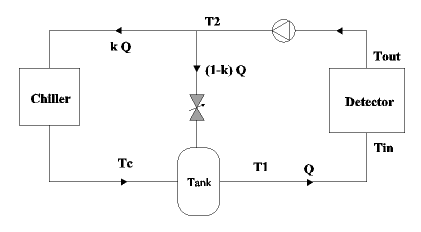
With the Module0 cooling facility was tested the concept of the cooling for the regulating circuit of Ecal. The principle tested can be resumed by the following diagram.

The chiller is a Lauda, the value of k has been set to 1/4.
The flow is split to reduce the influence of the temperature variation on Tc.
The Lauda was first regulating the temperature Tc, but as it could not answer a
variation of T2, it was further regulating T1.
The mixing tank introduced then a very long dead time that is making unstable the
regulation loop of the Chiller. It means that if there is a splitting, the temperature
regulated by the Chiller must be before any tank, and as close as possible of the Chiller
itself.
The Lauda was giving a sufficient precision in terms of temperature, but its regulation was not efficient enough. Anyway, this solution cannot be extrapolated to the size of the sub-detector, as the Lauda are limited in cooling power.